Lessons up front, justification later:
- Build or buy your capacitor FIRST, and then finish the rest of your loop design based on that capacitor
- Use a vacuum variable capacitor. From what I have experienced, many starting points with mag-loops nearly all end with the purchase of a vacuum variable cap. Save yourself time and money spent on preliminary work and just bite the bullet early.
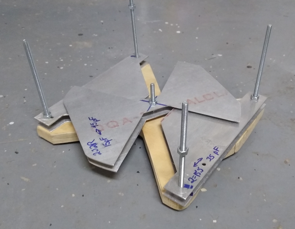
The twin copper plate capacitor shown above made a perfectly suitable capacitor, but could not be more difficult to adjust. Additionally my magloop goal was to handle the voltage peak of 100W transmission from 20m to 80m which would be at least 4500 Volts at approximately 7Mhz. The clamped plate capacitor stood no chance!
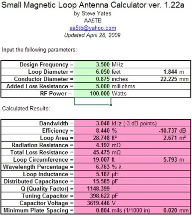
http://www.aa5tb.com/loop.html#cal
My mind first turned to making a 3d printed structure for the copper plates to adjust overlap, spacing, or even pumping in some type of liquid dielectric came to mind in order to make a variable capacitor. But the outcomes from two calculations stopped me from firing up CAD and carrying those designs forward.
- If using an adhesive dielectric, any remaining air gaps create a larger voltage gradient in that space than the surrounding dielectric material. Counter intuitively this happens even if the surrounding dielectric was much thicker than the airgap.
- Tangent loss coefficients looked like small numbers to me, but thankfully I came across a power loss calculation that showed dielectric losses REALLY stack up quick. (air gap or vacuum are really the only great paths forward for a loop)
As with most projects, my thought process went through many loops of ideas, until I finally got tired of thinking, started building, and the right answer revealed itself quickly. In this case I started with the assumption that air variable capacitors would be an easily acquired (as in the case from MFJ below) or fabricated option to cover my needs.
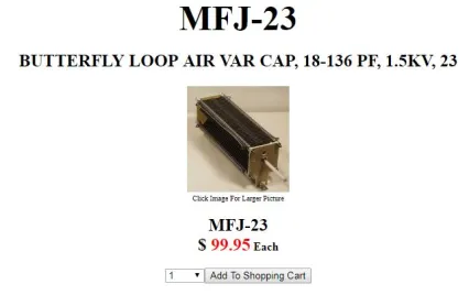
While both of those benefits turned out to be true, they are accompanied with two significant downsides. The first hit against air variables (AV) is that their Voltage rating isn’t the greatest in *most* cases when you’re chasing 5KV ratings. The 100 dollar MFJ capacitor shown above is typical in that it is rated for 18-136 pF, and 1.5KV. Better voltage ratings can be found through increased spacing of capacitor plates, but this has the result of reducing the capacitance rating of the device. Quickly one finds that a high value, high voltage butterfly capacitor becomes LARGE.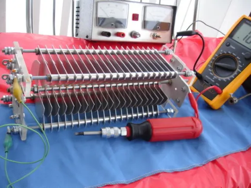
260pF/12kV Variable Butterfly Capacitor for a Loop Antenna kits VA6POP
The second downside to air variable capacitors is the ratio of max to minimum capacitance they can provide is somewhat restricted. To reach my goal of 20m to 80m I needed to achieve approximately 15 pF to 542 pF (more on that later). Many high voltage AV’s use a “butterfly” configuration to avoid conducting through the shaft slip ring, . This means that the cap essentially becomes TWO capacitors in series. The central shaft controls the overlap of an hourglass stack of plates across stator stacks. This is great to make the capacitor structural and to reduce losses through any central slip ring, but cuts the capacitance value of the setup in HALF. Additionally, even without the rotor plates present, the stators have some inherent capacitance just from being near one another this proximity effect from stator-rotor-stator even when completely unmeshed is what defines the minimum capacitance of that device. One design solution to lower this minimum capacitance is to move to a “split stator” design as shown below. This keeps the two stators farther apart, but at the expense of making a large cap even larger and increasing the resistance of your plate stack. Remember that in loops, milliohms matter!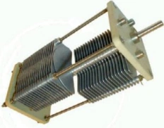
Material solutions to size and voltage rating
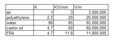
Capacitors are incredibly simple. a pair of conductive bits, separated by some dielectric media, and you just charge up that field between them until it eventually arcs if the voltage is too high. I started looking more into what material options for dielectric exist, and how changes in dielectric strength and constant effected plate spacing, and the resulting capacitance. Results looked GREAT at first. Plates spaced by only two thousandths of an inch will theoretically hold back 10KV if every bit of space between them is filled with polyethylene. Various materials were compiled from internet sources into the table below. K represents the dielectric constant which directly magnifies capacitance generated by two plates. KV/mm is the dielectric strength of the material. and V/m is simply another way of thinking about dielectric strength (obviously just a unit scaling)
https://en.wikipedia.org/wiki/Dielectric_strength
https://en.wikipedia.org/wiki/Relative_permittivity
So this table is exciting! With closer plate spacing permitted by high dielectric strength, and capacitance further magnified by the dielectric constant, a minimum separation D.I. water capacitor would create 856pF per square inch. Plenty enough to tune the whole mag loop. I considered flexible enclosures to vary plate spacing while using a liquid dielectric, syringe injection vary the amount of liquid between the plates, and of course just simple mechanical overlap control with some 3d printed structure. It all seemed too good to be true, and as further evidence I found this video of someone testing voltage breakdown of polyethylene to confirm my numbers (https://youtu.be/MPD7skZ8OSo?t=252).
Air-gap Arcing
Unfortunately while reading about capacitor dielectrics I came across a comment saying that even a small air gap between two dielectric covered plates would arc and ruin the capacitor. That comment proved correct when checked with the equation shown below, and the voltage across any small air gaps actually increases when the plates holding the source charge are coated in a dielectric. What this meant to my design is that simple polyethylene covered copper plates sliding to different mesh overlaps would not be able to handle the required voltage if even a thin layer of air remained between them. The setup would arc and penetrate the dielectric.
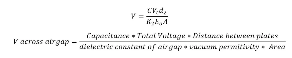
As an example, a two plate capacitor with 0.01″ polyethylene sheets coating both capacitor plates, and a 0.001″ gap between those dielectric sheets would fail. The thin polyethylene would successfully hold a 2,250V difference across their thickness, while the air gap is left opposing only 495 volts. This all sounds find until one checks the voltage gradient in the gap, and finds it is 650% of the dielectric strength of air. oops! SPARK! (and a ruined capacitor) It is not until the airgap reaches 0.06″ that the airgap voltage is workable, but now you are only getting 3pF per square inch of plate as compared to the initial 22pF/sqin if the plates had 0.001″ spacing. This problem disappears if you get rid of ALL the airgap between plates, but can you be certain you would *always* get rid of that gap?
The use of a liquid dielectric would ensure the gap between plates was always void of air, and it would be easy to vary the capacitance by remotely changing the liquid level with a small hose and a syringe back at my radio. BUT, physics does step in to squash this otherwise very nice idea….
Dielectric Losses
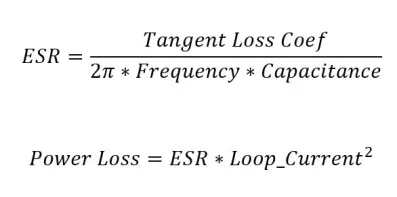
The calculation that killed this path of DIY capacitors for magloops was that of power dissipation inside the dielectric material. I had seen tables of “tangent loss coefficient”, but thought that *those numbers seem small…. probably not bad*. Yea ok… here is the real calculation I came across in a post by KH6AQ:
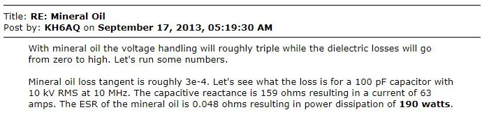
You can repeat his calculation for any given tangent loss coefficient, reactance, and effective series resistance (ESR) using the equation below:
http://www.rfcafe.com/references/electrical/dielectric-constants-strengths.htm
http://www.66pacific.com/calculators/small-transmitting-loop-antenna-calculator.aspx
The circulating current can often reach 20 to 40+ Amps during 100W transmission in a properly tuned magnetic loop, so dielectric losses (and heating) would occur relatively fast if the dielectric is absorbing 40+ watts. Also, this would substantially reduce the transmission efficiency of the loop itself. This single forum post and associated equation saved me a ton of work with dielectrics that probably would have just overheated and failed my requirements. Consulting the rfcafe listing of loss coefficients, water is large (0.005), FR4 PC board is worse (0.008), and polyethylene is one of the lowest of the solids listed (0.0002). Also notice that neither air nor vacuum have a listed tangent loss…. I’m sure the number exists for air, but it’s so small that one need not really bother (and any heated air would just drift away anyway).
Building a Butterfly Cap
With dielectric losses understood, my choices returned to an air variable capacitor, or a vacuum variable cap. Seeing that most any size of vacuum variable cap started at $150+ on Ebay, I set out to make a simple butterfly capacitor. Using a piece of scrap aluminum sheet, and a bag full of hardware from Atwoods (they sell it cheap by the pound) I sketched out various sizes of plates and began cutting everything out. The plates are so large because I wanted to get the maximum capacitance area from each while keeping cutting to a minimum. The decision for large plates was also driven by trying to avoid conducting through steel bolts, and friction connections at the nuts. Some butterfly capacitors go to the length of using all copper or aluminum hardware with welded joints to avoid the resistive losses of steel and contact connections. I figured if this capacitor worked out in its cheap form, then I would buy the more expensive upgrades later. 1/4 20 hardware was selected as that nut thickness gave me the desired voltage rating for the stack. Thinner spacing would have improved capacitance, but reduced the voltage rating significantly. Keep in mind the simple algebra equation isn’t exact, because the plate edges will create more severe field gradients. This is why corona starts on edges of components. You might shed energy through corona before you ever hear or see a spark.
Small Ratio of Capacitance
So at the point shown in the picture above it was working. I could turn the center part and achieve 15 to 45 pF with two rotor plates, or 15 to 35 pF with one central rotor. The minimum capacitance remained the same as I added another rotor plate because that minimum is principally driven by stator plate separation when the elements are completely unmeshed. So at this rate, each plate pair was adding ~20pF, so to reach my need of 540 pF I would need 27+ pairs of plates. What I had cut already should tune the loop for 20m… so it was time to go test it out!
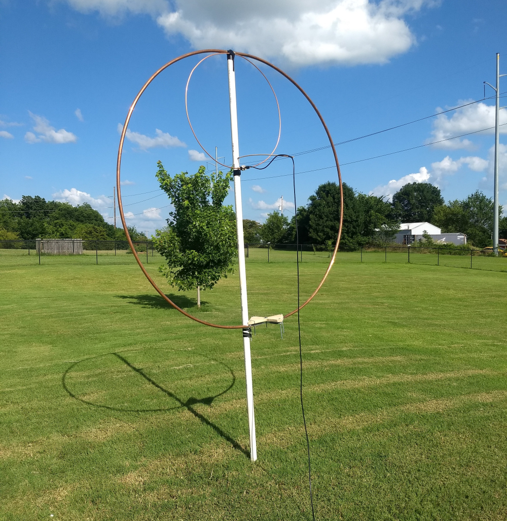
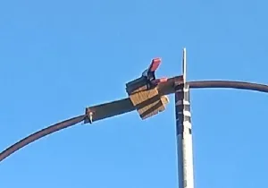
This setup worked fine through the 20m band. Manually adjusting the cap to tune the loop onto 14.074 for FT8 was a chore, and a remote tuner would definitely be required for the final version. After tuning I began transmitting at 5W, and stepped it up slowly in increments of 10W while checking for signs of arcing, or SWR changes. All was well up to 100W on 20m which implies the capacitor was fine up to 3KV!
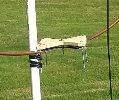
The coupling loop above was sized to match the wire length I tuned the loop with previously. It worked, but a coupling loop half the size worked just as well. The match on 20m was not too wonderful as pictured, but was brought below 2.0 SWR by bending more coupling loop material to be near the outer loop. This significantly improved the match of the antenna to ~1.4 SWR or better. The lowest the loop would tune with this butterfly capacitor was 10Mhz (WWV) and at that point the SWR was excellent at 1.2. The biggest detraction from this capacitor was that it was not quite mechanically stable enough to be a permanent solution. In the picture below you can see I just bolted it onto the copper loop in two places which pivoted regularly and made the loop a floppy mess to handle.
The butterfly cap test did help me determine that a vacuum capacitor was probably the way to go. A vacuum variable cap would have much lower resistance, easier adjustment, a higher voltage rating, and perhaps most importantly a much higher ratio of minimum to maximum capacitance that would enable the loop to work across my intended bands (20, 30, 40, 60, 80).
So off to Ebay I went and broke down to buy a nice Jennings 15pF to 1000pF 7500 Volt capacitor. Most vacuum caps on ebay are ex russian military hardware, so I was happy to find an option made in the USA. By the time I purchased more aluminum for a butterfly cap, made copper spacers, spent the time to cut and mount it all…. I would have spent more than the cost of this vacuum cap, and ended up with an inferior result. So after all of these checks, experiments, calculations, and fabrications… I should have just bought a vacuum variable cap to begin with. This is why I stopped to write all this down publicly in hopes that my expended time can be used to help someone else facing the same questions.


Many thanks KI5AIF this was the info I was seeking before starting a 40 to 10 M loop. I think you nailed all the important considerations, and knowing this history, I will try not to repeat some of it. Commercial loops are $$$$ and I would rather put these funds in that vac cap. I plan to add a stepper motor to the cap and tune remotely with a Rig Expert analyzer.
73
KX4VW